NES Zapper Experiments #1
In a recent Hackaday post
they spoke about bringing the old NES game Duck Hunt
back to life on modern televisions (LCD/Plasma/OLED). As I had a few NES Zappers lying around and an Oscilloscope, I figured I could do some experiments to determine the behaviour of the Zapper. Unfortunately, I don't have a CRT TV so I will be simulating a TV using an LED
What is the Zapper?
Chances are you already know what the NES Zapper is, if not feel free to catch up on Wikipedia
. The Hackaday article does a pretty good job of explaining how the Zapper was used in games, mainly focused on Duck Hunt as that is the most well known. I will give a brief recap of what's happening; The game Dunt Hunt is about hunting ducks, obviously, the player has 3 choices of game play modes - 1 Duck, 2 Ducks or Clay Pigeons - but they all work in a very similar way. I'll focus on the 2 Duck game mode as it demonstrates how multiple targets are handled. Once the game starts, 2 ducks start flying and you get 3 shots to shoot them both, this repeats 5 times for a total of 10 ducks. If you don't shoot the ducks in time they fly away, as you get to the higher levels the speed of the ducks increases until they become un-shootable If you miss a certain number of ducks, depending on the level, you lose.
To shoot the ducks you point the Zapper at the ducks on your TV and pull the trigger. The trigger input is monitored by the game, when the trigger is pulled the gun is tested to ensure it's detecting light, the next frame is rendered black, then in the frame after (or the next 2 frames after) a white target box is drawn where the duck is.
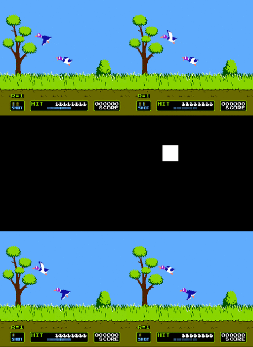
The black frame is used to ensure that the gun is pointed at the TV and not at another light source, the Zapper should register no light, if there is light then the gun is not pointed at the screen and a miss should be registered. For each of the next frame(s) the status of the gun is checked to see if there is light registered, if there is then the target corresponding to that frame registers as being hit.
All of this is fairly well known, I have simplified the process, and it may not be the same for every game, a bit but you should get the jist of it.
How the Zapper works
The Zapper is a fairly minimal device, a switch for the trigger and a photodiode with circuitry, and a lens for the target detection. The cable has four pins connected, 5v, ground, trigger, and detect, on the NES side of the connector there are pull-up resistors on the detect and trigger pins.

I performed a few experiments to work out some characteristics of the Zapper.
The first thing to do was understand a bit about how a CRT TV works, Wikipedia has a pretty decent article. This High Speed video of a CRT TV gives you an idea of what is happening, unfortunately a scanline takes ≈64μs to draw so you cannot see the actual line being drawn in this video. The phosphor on the TV is quite slow to decay >1 ms, but depending on the TV it will vary and the light gun has to be quite tolerant to these differences. Unfortunately I don't have a CRT TV so I have to approximate one with an LED. I made a few assumptions, I assumed that the Zapper would only "see" one very small portion of the screen - a portion of one scanline. This probably isn't the case, depending on the distance the gun is from the TV and the size of the TV it may have a view on different portions of the screen. As the target box is larger than one line I would expect the photodiode to detect light constantly over a number of scanlines.
To hook the Zapper up to the scope I cut the an extension lead for a NES controller and soldered the socket end to a piece of stripboard with some 4k7Ω pull-up resistors to mimic the internals of the NES controller port, and put a pin header to allow me to connect it to the scope or a microcontroller later. I used an Arduino to flash a blue LED (an RGB LED really, but I only used the blue part in the end) and to power the Zapper, I wired 5v from Arduino attached to the 5v pin on the Zapper and the same for ground. Once the LED was flashing I put the LED at the end of light gun barrel and hooked up the scope of the DETECT pin and a pin on the LED.
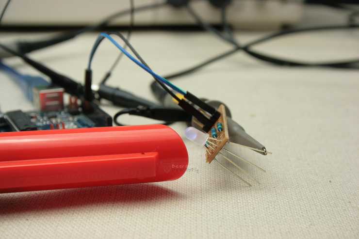
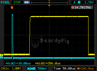
My first experiment was to strobe the LED on for ~10μs and off for ≈20ms (≈50Hz) and see what happened.
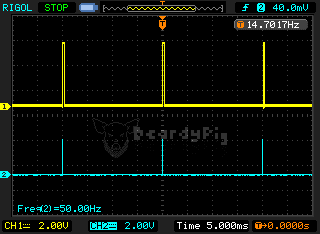
As you can see, the DETECT pin goes high when the LED is turned on - sweet!
Then I tried strobing the LED on for ≈2ms to see what happened.
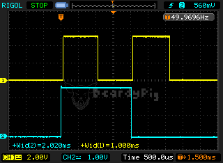
The result of this was a bit unexpected, the DETECT pin was triggered both when the LED was turned on and when the was turned off. This got me thinking that what I had read elsewhere about the lightgun only working with TV scan rates (15 kHz) was wrong. It appears any suitable length flash of light will trigger the sensor, maybe even a modern TV (more on this later!). The duration of the pulse from the lightgun on the DETECT pin is 1ms, this is the case as long as the flash of light lasts longer than ~16μs.
Pulses shorter than ~16μs produce erratic output on the DETECT pin. Pulses that are very long >1ms cause the light gun to set the DETECT pin high on both edges of the light pulse of 1ms.
Strobed an LED on for ~20μs and off for ≈20ms.
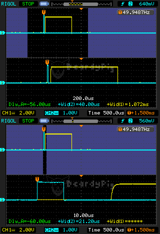
The delay between the light being turned on and the DETECT pin being set high is ~60μs, which is about the time is takes to draw 1 scanline.
Now I know a bit about what the lightgun is doing I think that it might work on a plasma TV. I plan to explore this in part 2 of the NES Zapper experiments.
Appendix: Arduino LED Flasher
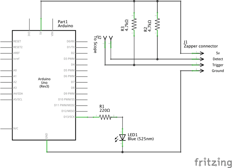
The Arduino was wired up to an LED with a 220Ω resistor on pin 13. Running the following sketch, it's easy to change the delays and recreate these experiments. I would have used a waveform generator, but I don't have one
void setup() {
  pinMode(13, OUTPUT);  // set pin 13 as the output pin for the LED
}

void loop() {
  // flash the LED at ~50Hz
  while (1) {
    digitalWrite(13, HIGH);
    delayMicroseconds(1);
    digitalWrite(13, LOW);
    delay(20);
  }
}
A the schematic diagram, drawn with fritzing .
Update: Read Part 2 of the NES Zapper Experiments
References: